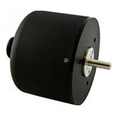
Ranges from ±30º to ±60º KEY FEATURES
DC Voltage Operation
Non-linearity
Absolute Measurement
SPECIFICATIONS
| MODEL NO. | DISPL. RANGE +CW, -CCW |
LINEARITY* | MAX. USABLE RANGE | LINEARITY USABLE RANGE | OUTPUT VDC | INPUT/ OUTPUT CURVE | TYPICAL TEMP. COEF. SPAN/ °F |
| 0600-0000 | ±30° | ±0.05% | ±40° | ±0.10% | 100 mV/° | 1 | -0.01% |
| 0601-0000 | 10°-70° CW | ±0.05% | 0°-80° CW | ±0.10% | 100 mV/° | 2 | -0.015% |
| 0602-0000 | 10°-70° CCW | ±0.05% | 0°-80° CCW | ±0.10% | 100 mV/° | 3 | -0.01% |
| 0603-0000 | ±60° | ±0.10% | ±80° | ±0.15% | 100 mV/° | 4 | -0.01% |
| 0603-0001 | ±60° | ±0.05% | ±80° | ±0.10% | 100 mV/° | 4 | -0.01% |
| 0603-0002 | 20°-140° CW | ±0.10% | 0°-160° CW | ±0.15% | 50 mV/° | 5 | -0.015% |
| 0603-0003 | 20°-140°CW | ±0.05% | 0°-160° CW | ±0.10% | 50 mV/° | 5 | -0.015% |
| 0603-0004 | 20°-140° CCW | ±0.10% | 0°-160° CCW | ±0.15% | 50 mV/° | 6 | -0.01% |
| 0603-0005 | 20°-140° CCW | ±0.05% | 0°-160° CCW | ±0.10% | 50 mV/° | 6 | -0.01% |
*Definition: Zero Base Terminal Average, expressed as a max % deviation of total range. CW defined as clockwise direction of shaft rotation, when viewed from shaft end.
COMMON ELECTRICAL SPECIFICATIONS
| REPEATABILITY | INTERNAL CARRIER FREQUENCY | 400 KHz | |
| RESOLUTION | Infinite | RIPPLE, MAX. | 20 mV P/P 400 KHz |
| CURRENT, INPUT | 30 mA Max. | ZERO ADJUSTMENT | ±3° |
| IMPEDANCE, OUTPUT | ZERO POSITIONS | See Output Curves | |
| MAX. ANGULAR VELOCITY | 1,440°/sec | FREQUENCY RESPONSE | > 1500 Hz |
| MAX. ANGULAR VELOCITY with output down |
18,000°/sec available (see “Ordering Information”, pg. 53) |
EXCITATION VOLTAGE Input > 18 VDC may damage unit |
15.00 VDC (see options, pg. 53) |
| INPUT POLARITY PROTECTED | OUTPUT SHORT CIRCUIT PROTECTED | ||
REMOTE ZERO OPERATION

Unless operating in a noise free environment, the lead to pin C must be shielded, as shown. The existing zero adjusted potentiometer in the Angular Displacement Transducer must be rotated fully clockwise before the remote zero control can function correctly. This remote zero control can function correctly. This remote function is useful in applications where it is inconvenient to access the adjustment screw on the transducer housing.

