
Ranges from ±0.05” to ±4.0” KEY FEATURE
6 to 30 VDC Excitation
Non-linearity
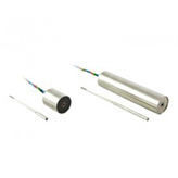
Stainless Steel Construction
SPECIFICATIONS - ELECTRICAL
| MODEL NUMBER | 0240-0000 | 0241-0000 | 0242-0000 | 0243-0000 | 0244-0000 | 0245-0000 | 0246-0000 | 0246-00005 |
| WORKING RANGE, ± Inches (mm) | 0.050 (1.27) | 0.100 (2.54) | 0.250 (6.35) | 0.500 (12.7) | 1.00 (25.4) | 2.00 (50.8) | 3.00 (76.2) | 3.00 (76.2) |
| MAX. USABLE RANGE, ± Inches (mm) | 0.075 (1.78) | 0.150 (3.75) | 0.375 (9.53) | 0.750 (19.1) | 1.50 (38.1) | 2.75 (69.8) | 3.25 (82.5) | 4.00 (101) |
| INPUT, VDC | 6.0 Min. to 30 Max. | 9.0 Min. to 30 Max. | ||||||
| NOMINAL F.S. OUTPUT, ±VDC with unloaded output | ||||||||
| @ 6 VOLT INPUT | 1.3 | 2.4 | 1.8 | 3.1 | 4.6 | 3.9 | 3.3 | N/A |
| @ 15 VOLT INPUT | 3.4 | 6.4 | 4.8 | 8.3 | 12.1 | 10.2 | 8.7 | 10 |
| @ 24 VOLT INPUT | 5.5 | 10.4 | 7.8 | 13.5 | 18.7 | 16.5 | 14.1 | 16.3 |
| @ 30 VOLT INPUT | 7.0 | 13.0 | 9.7 | 17.0 | 24.8 | 20.7 | 17.7 | 30.5 |
| INPUT CURRENT | 8.3 mA @ 6 Volt input to 52 mA @ 30 Volt input | |||||||
| 2 NON-LINEARITY | ±0.5% Full Scale Over Total Working Range, ±1.0% Full Scale Over Maximum Usable Range | |||||||
| INTERNAL CARRIER FREQUENCY, Hz | 13000 | 12000 | 3600 | 3400 | 3200 | 1500 | 1400 | 1400 |
| % RIPPLE, RMS (nominal) | 0.7 | 0.7 | 0.8 | 0.8 | 0.8 | 1 | 1 | 1 |
| OUTPUT IMPEDANCE, Ohms | 2500 | 3500 | 5200 | 5500 | 5600 | 5500 | 5600 | 5600 |
| FREQ. RESPONSE (3 dB down), Hz | 300 | 140 | 115 | 110 | 100 | 110 | 75 | 75 |
| TEMPERATURE RANGE | -65°F to +250°F (-54°C to +121°C) | |||||||
| RESOLUTION | Infinite | |||||||
NOTES:
Polarity of excitation must be observed for proper function. Reversal will not damage the unit.
Load Impedance of 50 KOhms minimum required for proper operation.
Output polarity will be positive on one side of null, negative on the other side of null.
Transducers are calibrated at 24 VDC.
Blue lead is more positive with respect to the Green lead when the core is moved toward the lead end.

DIMENSIONAL DIAGRAM

SPECIFICATIONS - MECHANICAL
| MODEL* | LINEAR RANGE | BODY LENGTH, A | ELECTRICAL CENTER, Ec | BODY MASS | CORE LENGTH, B | EXTENSION LENGTH, E |
| ±Inches (mm) | Inches (mm) | Inches (mm) | Grams | Inches (mm) | Inches (mm) | |
| 0240-0000__ | 0.05 (1.27) | 0.87 (22.1) | 0.34 (8.64) | 55.8 | 0.56 (14.2) | 1.9 (48.3) |
| 0241-0000__ | 0.10 (2.54) | 1.12 (28.5) | 0.46 (11.7) | 59.2 | 0.75 (19.1) | 1.9 (48.3) |
| 0242-0000__ | 0.25 (6.35) | 3.21 (81.5) | 1.44 (36.6) | 121.4 | 1.75 (44.5) | 1.9 (48.3) |
| 0243-0000__ | 0.50 (12.7) | 3.71 (94.2) | 1.69 (42.9) | 132.2 | 1.87 (47.5) | 2.4 (60.9) |
| 0244-0000__ | 1.00 (25.4) | 4.71 (120) | 2.19 (55.6) | 156.2 | 2.00 (50.8) | 3.2 (81.2) |
| 0245-0000__ | 2.00 (50.8) | 8.21 (209) | 3.94 (100) | 235.4 | 3.50 (88.9) | 5.2 (132) |
| 0246-0000__ | 3.00 (76.2) | 10.52 (267) | 5.09 (129) | 293 | 3.50 (88.9) | 8.4 (213) |
| 0246-00005 | 4.00 (101.6) | 10.52 (267) | 5.09 (129) | 293 | 2.00 (50.8) | 9.1 (231) |
* Model numbers ending with a “_” have multiple core options. All standard units will end with a 0 indicating a core assembly. This core assembly consists of a core brazed to an extension rod that terminates in 1-72 UNF-2A threads. If an option is not selected, option 0 will be provided.